The purpose of this blog is to demonstrate how to measure distance with the Kinect. The project uses Emgu (Computer Vision Library). Emgu is the C# version of OpenCV (Open Computer Vision). The following software example was taken from the Kinect SDK 1.8 Coordinate Mapping sample. The sample was modified to measure distance using the Depth Buffer.
How to take the Measurement
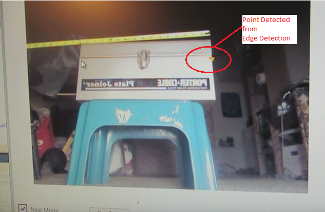
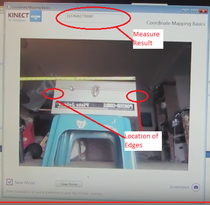
To measure the distance across the tool box, the user needs to collect 2 points as shown in the image. After the user has taken the 2 points, the result will show up in the top edit box as shown.
Theory of the operation
After the Kinect has collected the image, the software uses Canny Edge Detection to generate the edges of the object. The image on the right is the processed image after the Canny Edge Detector was applied.
Edge Detection
The actual edge detection is done in the black and white image. To get the point on the edge;
The user selects a line of pixels perpendicular to the edge know as the Region of Interest. This process returns an array of pixel intensities.
The location of the edge occurs where the pixel intensity has the greatest difference between adjacent pixels. For example if the array returned { 0, 0, 0, 200, 10, 40 }. The location of the edge is where the intensity goes from 0 to 200.
C# Code for Calculating Distance
The code works by the user clicking the mouse button in the video window to get a point in the image. The mouse click returns the depthPoint from the image. The point is converted to a 3D space by mapping the point to a Skeleton point. After the user has attained 2 points, the distance between the points is calculated by the SQRT ((P1.x-P2.x)^2+(P1.y-P2.y)^2+(P1.z-P2.z)^2).
The following C# code shows the process of getting a point from the video and converting it to a 3d point.
{
position = GetEdgePoint(MaskedColor, overlayImage);
A good reference for the project was “Beginning Kinect Programming with the Microsoft SDK” by Jarret Webb and James Ashley. The book is well written and has great examples. Chapter 8 “Beyond the Basics” has a lot of good utilities that were very useful. One example was converting between Bitmapsource and Bitmaps.
Limitations
The one limitation of the application; the results were not always consistent. Sometimes the edge detection did not detect the point, so you would need to take the point again. I am not sure if it is because the camera was not calibrated or the Depth and Image buffers were not aligned.
You are probably wondering what does Augmented Reality have to due with CNC milling. Augmented Reality would enhance the usability of the mill by using a camera. The camera would tell the mill where to move by detecting markers placed on the material to be machined. I came across a lot articles online about Marker Tracking. The goal is to have the camera detect the marker and calculate the postion on the material. Next, the mill would move to the position and start cutting the material.
Open Source Augmented Reality
There are many Augmented Reality libraries out there. The 3 libraries that I looked at were; ArUco toolkit, ARToolkit, and Glyph. I was looking for a library that would support 64 bit Windows and was based on OpenCV or Emgu. I chose the ArUco library for the marker tracking ability. For more information on the ArUco library refer to the following link;
http://www.uco.es/investiga/grupos/ava/node/26
https://sourceforge.net/projects/aruco/
There is a learning curve with the library, but there are many simple examples to start with. Calibrating the camera took a little time to get working that was me not the library.
The ARToolkit is a good library to use also. The ARToolkit also worked with the Unity Game Engine. The game engine looked like a popular package to use with Augmented Reality. The next area to look at would be understand how to integrate Unity with the project.
The versions of software I was using;
OpenCV Library 3.10
ArUco Library 1.3
ARToolkit V5.x
Visual Studio 2012
Windows 7 x64
Kinect SDK 1.8
Kinect Camera
The project started out using a Logitech web camera. Once the software was working the next phase was to use the Kinect camera. As the project progresses, the Kinect would be used to calculate the position of the marker in 3D space. The camera is able to measure the distance because it includes a depth buffer along with an image buffer. A plain old web camera only has an image buffer. With the depth and image buffers aligned in the video, a user can click mouse button in the viďeo window to get the distance reading (Z). The X and Y position would be derived from the measurement (Not sure about the accuracy of measurements).
Marker Tracking with the Kinect
The video below starts out with the Kinect tracking one marker. The second half of the video shows the Kinect tracking 24 markers. Initially the Kinect would only track 6 markers, because the image was reversed horizontally. This meant that the markers were also reversed. 6 markers were detected, because their orientation was symmetrical horizontally. Once the orientation of the video was corrected, then the Kinect detected the 24 markers.
The application is written in C++. The application is one of the sample applications provided with the library, but it had to be modified for the Kinect. Most of the work was getting the library to work with the OpenCV 3.1 and the Kinect SDK 1.8.
Most of the OpenCV applications I came across used a web cam, but not the Kinect. The code used for collecting images with the Kinect came from a blog by Rozengain “A Creative Technology Company Specialized in 3D”. The web site is http://www.rozengain.com
The next step is to make a version that works in WPF and C#.
The machine shown in the following video is a only prototype. It was a temporary platform to develop and test the software. To make a long story short. The real machine to be retrofitted for the CNC controls is actually in the garage. The problem I encountered is; the garage gets very cold during the winter months. So I built the machine so I can write the software inside a warm house during the winter months instead of the garage. After all most of the software was written during the winter.
The XY table was bought. It only cost $90 dollars. You can probably get one for less. All of the pulleys and belts were bought from Stock Drive Products (http://www.sdp-si.com/).
The X and Y motor mounts were the parts designed and machined by me. The plans are based off of design articles from the Home Shop Machinist Magazine (http://www.homeshopmachinist.net/). Roland Freistadt was the author. There are other plans out there.
The Z Axis was copied from a design on the website “CNC on a Budget” http://www.cnconabudget.com/. The design was simple and very straightforward and very inexpensive to make.
The CNC controllers are from JR Kerr Engineering (http://jrkerr.com/). The company has been around a long time. The prices for the control boards are pretty good. One board controls one axis, therefore you will need 3 of them for the XYZ axis.
I used an Xbox Joystick to move the stage. The software is based off of the open source project by – Jean Phillipe Steimetz. There is a lot that can be done with the Joystick. A lot of the buttons on the Game Controller can be assigned functions such as setting the origin of a coordinate system or setting the tool offsets. You can probably use it to navigate the UI. There is more to come on this section.
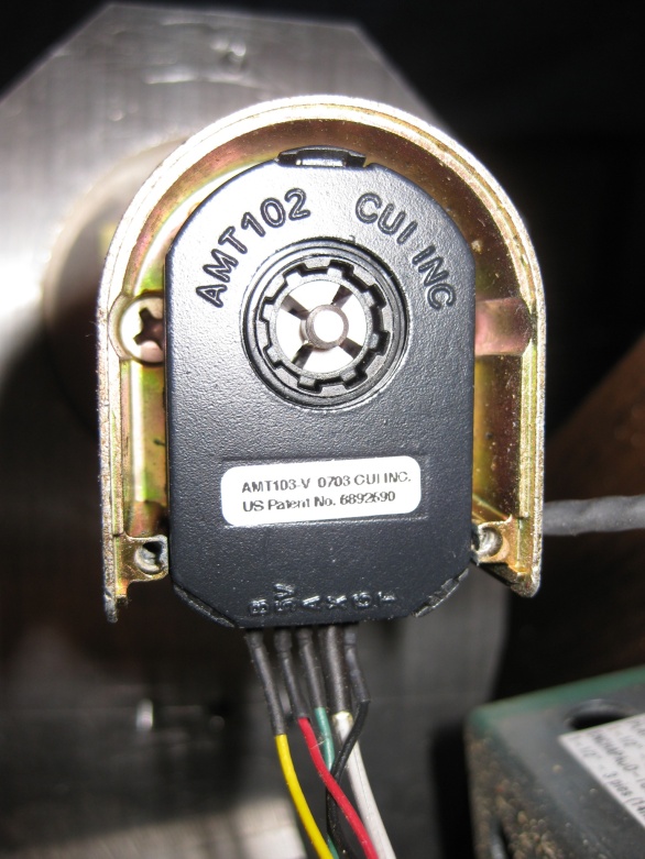
AMT102 Encoders from CUI INC
The motors used for the mill were bought from a surplus store online. The price was right, but they needed new encoders. Encoders are the most important part of the servo motor. The device keeps track the motors location. The mill uses the AMT102 encoder from CUI INC. You can buy them from Digi-key Electronics.
This is the link to the encoder kit. The kit includes the following;
7 shaft adaptors that fit most motors.
Encoder itself.
Encoder housing to mount to the motor.
Tool to mount the encoder.
This is what the encoder looks like
The setup was relatively straightforward. It took about a few minutes.
The advantages of this encoder over others;
The CPR can be configured. At least for this model.
The encoder kit comes with shaft adaptors to fit the common sizes of shafts. This option gives the user more flexibility to move the encoder to a different motor if needed. Other manufacturers do not have this option.
Lower cost. These encoders cost less than their counter parts from other manufacturers. This model is around $28.
The encoders do a good job controlling the motor position. In the video, the mill cuts out a pretty good circle.
Therefore, the encoders are doing their job well.
Machining the parts for the CNC mill
When I started designing the machine, I knew very little about how to machine parts. Thanks to the machinist and other employees at work they were able to instruct me. I value their help and guidance. Blogging about setting up a simple machine shop could take an infinite number of blogs, but this will be brief.
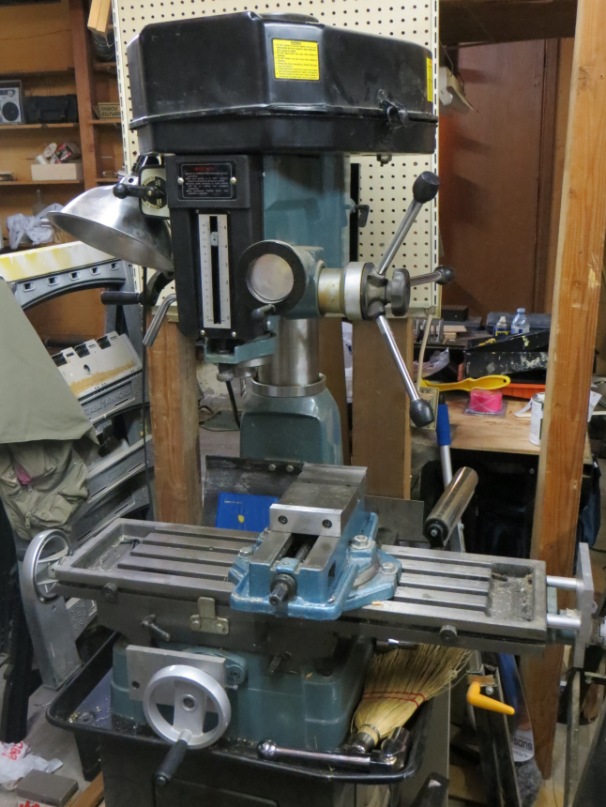
I have a very simple machine shop. The 2 main pieces of the shop are a variable speed band saw and a mill drill. The mill drill was purchased from ENCO. It is a good machine for the price, but I would recommend getting the one from Jet Tools. The one in the photo is the 2 hp version. I would recommend getting the smaller version with the 1 hp motor. The photo shows the mill with the vice mounted on the table.
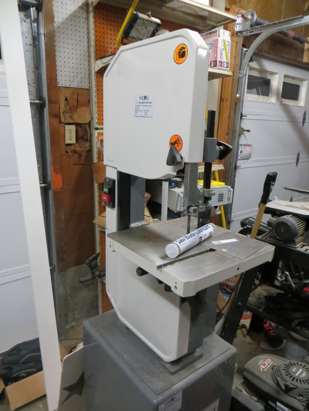
The band saw was purchased from Wilton. You can buy a similar saw from MSC Industrial, Grizzly Tools. When you cut metal the blade needs to run slow(100 sfm or slower). The saw can be configured to accommodate the slow speeds. The saws you see at Home Depot might not work, because they cut too fast(3000 sfm). If you are cutting metal with a fast moving blade, the blade will get hot and break. Or it will wear the teeth off the blade in minutes.
The next items you need;
Machine vice to hold down your parts
Caliper to measure your parts
set of drill bits and pilots.
set of reamers.
set of collets.
set of parallels.
set of end mills.
Bore head and cutter sets.
simple punches to start pilot holes
clamping sets.
a tapping set (inch and metric).
Most of the tools were purchased from MSC Industrial. When you are first building your shop, I recommend purchasing the less expensive tools. MSC Industrial provides different grades of tools. I recommend generally (but not always) buying the “Import” grade. They are much cheaper in price.
If you discover you like machining and you want to make a living at it, then buy the professional grade of tools. When you are running a shop for profit, you need to have the best and most reliable tools. Having cheap tools and breaking on you can be expensive. If the tool breaks, production shuts down and you lose revenue. If you send someone out to replace the tool, then you increased your production cost. Added labor means added cost.
The aluminum was purchased from MSC Industrial Supply. They have 2 day shipping. There are other places that sell the metal at cheaper prices.
Software for CNC Machine
I used CAMBAM for the CAD/CAM. This is a great software package. Their online videos for training are the greatest. You can learn to use the software in 10 minutes. You won’t be an expert, but you will be good enough to use it.
The work flow for the CNC mill is as follows;
Create the G-code file from CAMBAM.
Run the CNC mill software.
Move you stage to the desired position on the stage.
Load the G-code file into the CNC mill Software. The software displays the G-code file in the control panel.
Hit the Run button on the CNC mill Software UI.
The mill starts cutting the material.
The video will show you how to create a G-Code file from a CAD file drawn in CAMBAM.
The software is written in WPF C# and C++. Actually, most of the effort was writing the software to control the machine.
All the low level functionality resides in native C++ DLLs. The main functionality of the DLLs controls the stage and cutting path. One DLL parses the G-code to be read into the stage and path DLLs. Other DLLs provide the mathematical functions to transform the coordinate system of the machine.
The User Interface is written in WPF. I started using Windows Forms, but WPF had better support for Graphics. The UI was separated from the functionality to minimize the dependency on the low level functionality. Switching from the Windows Forms to WPF was a minor change.
Also I realize the importance of unit tests. I wrote unit tests for the lower level functionality. The unit tests forces you to minimize the dependency between each object. So if you wanted to create another type of project, you could reuse the code.
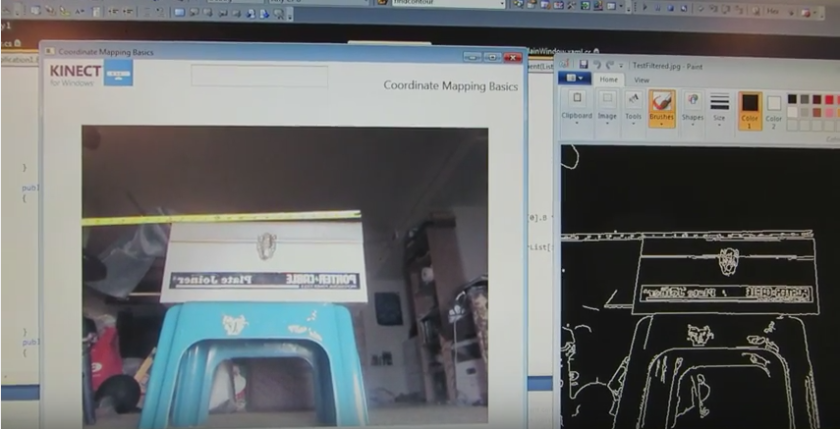 After the Kinect has collected the image, the software uses Canny Edge Detection to generate the edges of the object. The image on the right is the processed image after the Canny Edge Detector was applied.