Posted in CNC Router, Computer Vision

Updating your old CNC machine (Augmented Reality JoyStick Part 5)

Introduction

The purpose of this article is to explain how to update your old CNC machine.  Also a another reason for this article is to record what I did so I can reference it later.  I guarantee, 6 months from now I won’t remember.  This article was written assuming you have some experience with the KFLOP motion controller or any other motion controller.  Also, good wiring skills are needed to connect encoder/motor to the motion controller.

About the old machine

The machine was old, but it was in good condition.  The table moved as expected. You can turn the lead screws on each axis and move the axis.  This task was to make sure that the lead screws were not locked.

DC Servo Motor

This is my 3rd machine that I have worked on.  Refurbishing the machine went faster than expected, because most of the parts were still working.  The machine used old DC Servo motors with analog tachometers.  After all the machine is over 20 years old.  What do you expect from an old machine? 


Modifying DC Servo Motor and Analog Tachometer

To update the motors, I removed the tachometers and replace them with encoders.  It was a very small investment in time and money.

The image below shows the original motor with tachometer.

Motor and Analog Tachometer

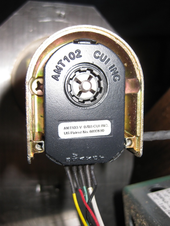
Replacing the Tachometer with Encoder.

The image below shows the motor with the encoder.  Replacing the tachometers with encoders simplified the motor.  I used the AMT102 encoders from CUI, Inc.


Incorporating KFLOP and Snap Amp

I used the Dynomotion KFLOP Motion Controller again for this project.  What is different with this new machine from the previous CNC machines?  I used the Dynomotion Snap Amp to drive the servo motors instead of the Gecko drives.  This turned out to be a good decision;

  • The minor downside of the Snap Amp; it costs more than the Geckos. The Snap Amp costs $400, but controls 4 axes.  If you only need 3 axis, 3 Geckos will cost you $114.95/each for a total for $344.85.
  • The Snap Amp was easier to wire than the Geckos.
  • Dynomotion provides all software to tune the PID parameters for the Snap Amp. Tuning the Amplifier was done without any manual adjustments to the hardware. The Gecko drives required manually tuning by adjusting a potentiometer on the drive.


XBox Joystick

We are using the XBox Game Controller to move the machine.  It works well for what I want it to do.  The good thing about the controller, you can customize the joystick to do more than just move the machine.  In this demonstration, functionality was added to the X, Y, B button to zero out the axes.

Just a tip.  If you don’t want to spend a lot of money on XBox Joystick, you can buy one at Goodwill for $6 or $7.  I bought my second joystick there.  It works as good as the newer one.


Getting the Motion Control System to work

This took me about a few hours to get the first motor to move because I was a little sloppy with the wiring.  Make sure your wiring is good especially between the encoders and the KFLOP.  Bad wiring will cause the machine to move unexpectedly.  After working on the machine, I am a firm believer in using the e-Stop.  If you machine goes out of control; just hit the e-stop.  Whatever you do, take your time with the wiring and invest in good crimping tools

Also, It took me a while to figure how to write the C program to move the stage.


int main()

{

    WriteSnapAmp(SNAP0+SNAP_PEAK_CUR_LIMIT0,9);
    WriteSnapAmp(SNAP0+SNAP_PEAK_CUR_LIMIT1,9);

 // clamp supply to 90V
    WriteSnapAmp(SNAP0+SNAP_SUPPLY_CLAMP0,SNAP_CONVERT_VOLTS_TO_ADC(70.0));
    WriteSnapAmp(SNAP0+SNAP_SUPPLY_CLAMP1,SNAP_CONVERT_VOLTS_TO_ADC(70.0));

 // enable supply clamping
    WriteSnapAmp(SNAP0+SNAP_SUPPLY_CLAMP_ENA0 ,1);
    WriteSnapAmp(SNAP0+SNAP_SUPPLY_CLAMP_ENA1 ,1);
}


This code will allow you move the motors from the KMotion Step Response dialog.  I would test each axis.


How to Create the C Program for the KFLOP and Snap Amp.

Creating the C program to control the SnapAmp was a little tricky.  I am assuming your machine has 3 axis.  Basically, I converted InitKStep3Axis.c program to control the Snap Amp.

Here are the steps.


  1. Copy InitKStep3Axis.c in C:\KMotion433\C Programs\KStep to C:\KMotion433\C Programs\SnapAmp.
  2. Go to the C:\KMotion433\C Programs\SnapAmp.
  3. Rename InitKStep3Axis.c to InitSnapAmp3Axis.c.
  4. Open InitSnapAmp3Axis.c.
  5. Paste the following code below the Main ()


WriteSnapAmp(SNAP0+SNAP_PEAK_CUR_LIMIT0,9);

WriteSnapAmp(SNAP0+SNAP_PEAK_CUR_LIMIT1,9);

// clamp supply to 90V

WriteSnapAmp(SNAP0+SNAP_SUPPLY_CLAMP0,SNAP_CONVERT_VOLTS_TO_ADC(70.0);

WriteSnapAmp(SNAP0+SNAP_SUPPLY_CLAMP1,SNAP_CONVERT_VOLTS_TO_ADC(70.0);

// enable supply clamping

WriteSnapAmp(SNAP0+SNAP_SUPPLY_CLAMP_ENA0 ,1);

WriteSnapAmp(SNAP0+SNAP_SUPPLY_CLAMP_ENA1 ,1);


  1. Remove the command KStepPresent=TRUE.


The top of the program should look like.

Tuning the DC Servos.

Once you have the program you can start tuning the servos.  Dynomotion provides all of the software to tune the system.  Of course you need to wire the encoders to the KFLOP.

Before you apply power to the motors, run the KMotion.exe and hit the “Axis” menu.  This page displays the status of the each axis via encoders.   When you turn the motors manually, you will see the counts change for each axis.

Next wire the power up to the motors and the Snap Amp.

Here are the steps.

  1. Turn on the Power.  Run Kmotion.exe.
  2. Open, Compile and Run the initSnapAmp3Axis.c.

3. Open the Config Dialog.

4.  Open the Step Response Dialog.

5.  On the Step Response Dialog under the “servo” box.

Hit the “disable” button to disable the servo amp.

Hit the “Zero” button.

Hit the “Enable” button to re-enable the servo amp.

6.  To Tune hit the Step button.  You should see the output as shown above.

7.   Change the P, D, I values in the order specified until you get the output as shown below

8.  Repeat the steps for the other axes.  For more information refer to the KFLOP manual.


Posted in CNC Router

How to connect the Omron EE-SX671 Limit Switch to the KFLOP

Augmented Reality JoyStick Part 2

Limit switches are very important for machine safety and longevity.  The switches prevent the machine from moving past its mechanical limits.  When the machine reaches the limit, the switch sends a message to the motion control system to disable the motor.  This is especially critical when the stage is moving at high speeds.  Without the switches, parts can fly off the machine and potentially injuring the operator.  This project uses the Omron ee-sx671 which is an optical switch.

The Basic Circuit

The switch is just like any switch.  The switch is connected to digital input on the Dynomotion Snap Amp with a pull up resistor.  Here is a simplified version of switch.

The EE-SX671 is an optical limit switch

The ee-sx671 is an optical switch.  The sensor operates by sending a beam of light between the slot.  One side is the emitter the other is the receiver.  When the light is blocked between the emitter and receiver the switch changes state.  The advantage of an optical it is immune to electrical noise.  The disadvantage is it is affected by external light.

Know the configuration of your switch PNP or NPN

Since the part number is EE-SX671 and there is no P or R after the number.  The part is NPN.  Its very important to know the difference.  If the part is hooked up wrong it could damage the part.

Here is the PNP configure.  We are not going to use it.  We will keep this for future reference.

Some of the specifications of the switch

The important information to know is the voltage and the maximum current it can handle.  The switch will operate from 5 to 24 VDC, and can handle 35 ma max.

Connecting the switch to the Snap Amp

The following circuit is the DIO signal to the Snap Amp.  We connect the 5 volts of the switch to OPTO_PLUS signal.  The 470 ohm resistor the switch will draw 10 ma.  The current is well under the 35 ma limit.

Next we connect the OPTO_NEG signal to the OUT signal of the switch.

Each axis requires 2 switches; one for the min and one for max position.  We only need one 5 Volt power supply for all of the limit switches.

The limit switches are connected to;

Axis

Signal on Switch

Signal on Snap Amp

PIN Bit (SnapAmp #0)
X min + 5V OPTO_PLUS_0 32 72
OUT OPTO_NEG_0 31
X max + 5V OPTO_PLUS_1 34 73
OUT OPTO_NEG_1 33
Y min + 5V OPTO_PLUS_2 36 74
OUT OPTO_NEG_2 35
Y max + 5V OPTO_PLUS_3 38 75
OUT OPTO_NEG_3 37
Z min + 5V OPTO_PLUS_4 36 76
OUT OPTO_NEG_4 35
Z max + 5V OPTO_PLUS_5 38 77
OUT OPTO_NEG_5

37


Defining the Limit Switches in the KFLOP.

How do you use the information in the KFLOP.  You came to the right place.


Step 1:  Run KMotion.exe and Load the C Program for your setup.

You should see something like this dialog.

Step 2:  Open the “Config & Flash”

This is where you set the limit switch parameters.

Step 3:

Open the “Digital IO” dialog for the Snap Amp.  Make sure you connect the 5 volts to your limit switches.  You should see the following dialog.

Place a piece of paper between the slot of the limit switch.  You will see the state change in the check box from UNCHECKED to CHECKED.  Initially, I was not sure if the “Unchecked” state was HIGH or LOW.  The “Unchecked” state is low.  You might want to verify this yourself.

The C program I am using seems to work.  The KFLOP definitely stopped motion when I moved into the limits.

Best of Luck setting the limit switches.  Don’t forget to export the settings and save your program.


Posted in CNC Router

DIY CNC Engraving with the KFLOP and CAMBAM

Hello, I am back again.  I was side-tracked working on an Open Sourced PLC which I will cover in another post.  This post is about engraving patterns using your DIY CNC Mill with the KFLOP and CAMBAM.  CAMBAM has a feature to engrave patterns easy by simply opening a bitmap into CAMBAM.  It is so easy, a Caveman can even do it.  When you open a bitmap in CAMBAM, CAMBAM converts the edges in the image to a polyline.  I have provided the instructions and video to do the engravings.

How to open an Image in CAMBAM.

In this section I used the Boston Marathon logo as an example.  The logo looked like a fun project to do.  Also, I am a runner.  My wife and I ran the marathon in 2013.  Here are the following steps.

Step 1. Open the image from the “HeightMap Generator” under the CAMBAM “Plugins” menu as shown below;

Step 2.   Open the image into CAMBAM

Step 3.  Set your “HeightMap Generator” options.

Be aware that the XStep and YStep size are important.  The smaller size produces a better engraved image, but it takes the machine longer to carve the pattern.  A 4″ x 4″ piece of wood with a 0.04″ step size and feedrate 6″ inch/min will take about 2 hours.  With a 0.02″ step size, the same part will take over 3 hours.  This blog will show the difference between the engravings.


Step 4.  Generate the HeightMap

Step 5.  Generate the Tools paths and G-Code.

Video of CAMBAM generating G-Code from a Bitmap.

The video below will show you how to generate G-Code from the “HeightMap Generator” in CAMBAM.


Video of the CNC Mill engraving the Image on wood.

This video shows how the machine engraves the Boston Marathon Logo on the a CNC machine.  The CNC machine is using the Dynomotion KFLOP to perform the engraving

.  CAMBAM generated the G-Code from a Bitmap.

Final Products.

Before, I engraved the Boston Marathon Logo, I started with a business card to test the first engraving.  I took a photo of the business card and converted it to a black/white bitmap.  The black/white bitmap seemed work better than the color.

The business card is from Run 26 which is a running store in Mill Creek Washington.  If you want to get in shape for long distance running, this is the store.  They can help you select the right gear for you to start running.  They cater to all runners;  fast and slow, old and young.  The owner is a awesome and knowledgeable coach.

Engraving with different Step sizes.

The step size determine the quality of the engraving.  The image on the left was engraved with the steps sizes set to 0.04″ for both X and Y.  The image on the right was used 0.02″ for both X and Y, but took over 3 hours.  The engraving process was stopped after 3 hours.  It would have taken another hour.

If you have any questions or comments please contact us.

Also best of luck to the runners in the Boston Marathon tomorrow April 17, 2017.


Posted in CNC Router

An Affordable DIY Manual Mill CNC conversion with the KFLOP

The purpose of this post is to present an Affordable DIY Manual Mill CNC conversion using the KFLOP Motion Controller.  If you look on the web site, https://www.automationtechnologiesinc.com/, you can get most of the parts for under a thousand dollars.  You will have to buy the KFLOP from another vendor, because Automation Technologies does not sell the KFLOP.

item Description Price Total
1 KFLOP Motion Controller 249 249
3 Gecko Servo Amplifiers 114 342
3 Motors 350 oz-inch 79.95 239.85
3 AMT Encoders 38.95 116.85
947.7

Once you have the parts for the 3 axis machine, you will need to figure out a way to connect the motor to the machine.   This is only an estimate based on the following components.

  1. 2 timing belt pulleys (around $12 each),
  2. 1 timing belt around $15.
  3. 1 idler pulley and tighter around $100.
  4. 6″ x 24″ x 1/2″ aluminum around $40.
  5. 1 clamp to idler.

It will cost about $500 for the 3 axes.

If you have a machine shop or have access to one and you do the work yourself, your CNC Conversion cost is about $1,500.  However, this is excluding the cost of the CAD/CAM software.

Just for review, CNC stands for Computer Numerical Control.   A computer controls the movement of the Mill.  The CNC machine operates by the user doing the following steps;

  • Set the part onto a fixture with respect to work and tool offsets.
  • Load a G-Code program, to make the part, into the CNC control software.
  • Runs G-Code to machine the part.

I will explain more about the G-Code.

G-Code.

The g-code files tells the machine what to do and where to move.  You can find a good overview of G-code at this link

http://www.cnccookbook.com/CCCNCGCodeRef.html

G-code commands can be classified as Motion, Coordinate, Compensation, and Canned commands.  The most common Motion commands are G0, G1, G2, G3;

  • G0 – Tells the machine to move to a position XYZ.  The move is not in a straight line.
  • G1- Tells the machine to move linearly to a position.  During a linear move the mill move in a straight line.  Each axis moves and stops at the same time.  It is also known a coordinated move.
  • G2, G3 Tells the machine to move in a circular motion.

The Coordinate type commands would be G17, G18, G19 which allows you to select XY Plane, YZ Plane, ZX Plane respectively. 

The Compensation type commands such as G52 to G59 are used to set work and tool offsets on the machine.  

Canned commands such as, but not limited, G81 to G89 are used for drilling, boring, tapping.

This paragraph is only scratches the surface about G-code.  Refer to the above link for more details.

The CNC mill conversion 2.0 using the KFLOP

If you have read my post “DIY CNC Demo Using CAMBAM”, you would recognize that the new mill uses a lot of the mechanical parts from the old mill.  The old mill was prototype to verify that the design worked as expected.  It can do quite a bit of tasks, but it can only handle small jobs, because the motors are smaller and low power.  The new mill is larger and suited for industrial applications, and it uses larger motors.  The newer mill incorporates the same mechanical design, but it will also have;

  • New Servo Motors-sized better for the larger Mill/Drill.
  • New Motion Controller Card (Dynomotion KFLOP).
  • 3 Gecko G-320X Servo Amplifiers.
  • 3 additional mounting plates to connect the motor assemblies to the machine.

Originally, I was going to use the Gecko amplifiers with the Kerr Motion Control Cards, but I was not sure if they were compatible.  Besides I wanted to try something new and experience the KFLOP in action.

Old CNC Mill


New CNC Mill


The Dynomotion KLOP Motion Controller

The KLOP motion controller was recommended to me by a friend (Eric) at work.  Eric’s CNC mill broke down and he was going to fix it using the KFLOP.  He decided to use the KFLOP, because the parts for his old mill were too expensive.  He encouraged me to buy the KFLOP, so I bought the KFLOP.  I discovered that the KFLOP has a lot of nice features;

  • Controls up to 8 Axis Servo or Stepper motor.
  • USB interface.
  • Provides a G-Code Interpreter (Open source).
  • Provides good software examples.  The application KMotionCNC.exe, provided with the samples,  is a complete CNC solution.
  • The software can also be used by the .NET Framework.
  • Provides good documentation.
  • Only costs $250.
  • You can use a Game Console to move the stage.

The new mill requires 1 KFLOP motion Controller, 3 Gecko Servo Amplifiers and 3 Servo motors with encoders.   As shown below, each axis requires 1 servo motor.

Each motor uses an Incremental Encoder.  I recommend purchasing the encoders from US digital or AMT CUI INC.  I favor the encoders from AMT CUI INC because of the cost/performance ratio.  Check the prices for both manufacturers.  If you want a 2048 count encoder from US Digital it will cost about $76.  The similar product from AMT CUI INC would cost around $23.  If you are going to sell the CNC machines professionally you might consider US Digital.

KFLOP and Gecko Servo Amplifiers


Attaching the Motors to the machine.

Attaching the motors to the Milling machine took some thought.  This task required drilling 7 holes into the machine itself; 2 holes for the x-axis; 2 holes for the y-axis, and 3 for the z-axis.  It was a dreaded task.  Potentially ruining your machine is not a good feeling to have.

I don’t guarantee this is the best and only way, but it works.  Each axis required an additional mounting plate to connect the motor assembly.  Also, spacers were required between the mounting plate and the machine so the timing belt would be parallel to the motor assembly.  You will see this in the annotated X-Axis image.  The Z-Axis did not require spacers.  You will also see an annotated Z-Axis image.

Additional Machining for the X, Y and Z axis pulleys

Both the X and Y axes use a 2 ¼“ diameter pulley that needed modifications.  The bore diameters needed to be expanded from ¼“ to 7/10”.  To increase the bore diameter, I recommend using a boring head rather than using a drill bit.  Finding a drill bit with the exact diameter takes time.  When you re-drill the bore with a drill bit, the bit will make the hole off centered.  So when the pulley turns it will wobble.  Using the bore head does not have this problem.  The bore head can be adjusted easily for any size diameter.

The pulleys hubs needed to be machined so they would lock onto the axis of the mill.  If you remove the crank handle from the XY Table; this what the pulley needs attach to. 

Location to attach the Axis pulley


The modified pulley has a larger bore diameter and the hub was machine to interlock with the axis.  Basically you use a smaller end mill and cut straight across the hub.  The first cut is easy.  The second cut requires you to measure the arc distance on the mill axis.


Axis Pulley Interlocking with the Axis

The pulleys and timing belts were purchased from “Stock Drive Products and Sterling Instruments”.

The tools such as the bore head, end mill, drill bits were purchased from MSC Industrial.

 X-Axis Motor Assembly


 Y-Axis Motor Assembly

The work on the Y-Axis required the same work as the X-Axis.  The only difference is the mounting plate and the length of the spacers.

Y-Axis

 Z-Axis Motor Assembly

Attaching the Z-Axis motor assembly was about the same effort.  The assembly required; an additional mounting plate, extra shaft extended, and a shaft coupler.  Spacers were not needed.

Parts needed to attach the Z-Axis


Adjusting the PID (Proportional–Integral–Derivative) settings for each  Servo Motor Drive.

Setting these values were tricky at first.  It is best to start adjusting 1 motor without it attached to the machine.  Basically, adjust the PID values, on the Gecko amplifier, to the lowest settings.  Follow the instructions provided by Gecko.  Once you have the power and encoder lines hooked up to the amplifier, apply the minimum 18 volts.  It is best to start with the lower voltage, because the motor oscillations tend be worse with larger voltages.  Increase the voltage until the motors start oscillating.  Adjust the PID settings by turning the potentiometer on the side of the amplifier.  The “P”, “I”, and “D” are marked on the side of the amplifier.

  1. Turn the potentiometer for “P” so the oscillation stops and the motor is only humming.
  2. Turn the potentiometer for “D” so the humming decreases.
  3. Turn the potentiometer for “I” so the humming decreases even more.

After you connect the motors to the machine you might need to readjust the PID settings.  I ran into this problem when I was trying to control the machine.  The motor would move the machine in one direction without problems, but it vibrate in the reverse direction.

Creating the Initialization code for the KFLOP.

This section covers setting up the machine configuration, input/output channels, limit switch options.  The objective is to provide an overview of creating the “Initialization code” rather than repeat the manual.   The KFLOP user manual covers the task in detail.  

The main part to remember is to get the “Configuration”, and the “Step Response” Dialogs.  Both of these dialogs need to be open.  Select the menu options as shown in the image below.

Kmotion “Config & Flash” and “Step Response” Menu

On the dialog you will need to set the following.  This assumes your amplifier is setup for “Step” and “Dir” mode.

  • Hit the “Load Channel” button select KStepAxis0.mot for x-axis.
  • Set the Channel number.  For the x-axis it will be 0.
  • Set the Axis Mode as shown below.
  • Set your Input/output Channels.
  • Set the IO numbers for the limit switches.  This can be done later.
  • On the Step Response dialog set your PID, velocity and acceleration.
  • Hit the move button to set the step response.
  • Repeat for each axis.
Configuration Dialog


Step Response Dialog
  • Next, on the Kmotion.exe, hit the “C Programs” button.  Load a default program such as C:\KMotion433\C Programs\KStep\InitKStep3Axis.c
C Programs Dialog
  • Save the program as another program such as InitKStep3Axis-12-22-2016.c.
  • From the “Configuration” dialog hit “Export All to Open C Program” to update your setup C program.

Remember the name of the C program that you saved.  You will read this program from the KMotionCNC.exe.

YouTube has a good video for the KFLOP – “KSTEP Introduction – Getting Started with KSTEP Stepper Driver”

KMotionCNC application.

This application is a complete CNC solution.  The application provides a CNC Control Panel, G-Code Interpreter, G-Code Viewer.  The YouTube video, “KSTEP Introduction – Getting Started with KSTEP Stepper Driver”, and KFLOP user manual explains the application in detail.

The “INIT” button calls the C program that you saved in the previous section.  The video show you how to set the button to point to the C code.

KMotionCNC


Video of the New CNC Mill in Action.

The new mill uses the old mechanical design from the previous CNC mill.  Just to reiterate the machine uses the following parts;

  • KFLOP Motion Controller from Dynomotion.
  • Gecko g-320X Servo Amplifiers.
  • Servo Motors (300 oz/in XY axis, 240 oz/in for Z axis).
  • Encoders came with the YX motors.  Only the z-axis required a new encoder from AMT CUI.
  • XBox Joystick

The following video will show you how to run the KMotionCNC.exe application.

Xbox JoyStick

Video Of the Retrofitted Mill

If you have any questions or comment please let me know.


Posted in CNC Router

DIY CNC Demo using CAMBAM

Building the CNC Machine

The machine shown in the following video is a only prototype.  It was a temporary platform to develop and test the software.   To make a long story short.  The real machine to be retrofitted for the CNC controls is actually in the garage.  The problem I encountered is; the garage gets very cold during the winter months.  So I built the machine so I can write the software inside a warm house during the winter months instead of the garage.  After all most of the software was written during the winter.

The XY table was bought.  It only cost $90 dollars.  You can probably get one for less.  All of the pulleys and belts were bought from Stock Drive Products (http://www.sdp-si.com/).

The X and Y motor mounts were the parts designed and machined by me.  The plans are based off of design articles from the Home Shop Machinist Magazine (http://www.homeshopmachinist.net/).  Roland Freistadt was the author.  There are other plans out there.

The Z Axis was copied from a design on the website “CNC on a Budget” http://www.cnconabudget.com/.  The design was simple and very straightforward and very inexpensive to make.

The CNC controllers are from JR Kerr Engineering (http://jrkerr.com/).  The company has been around a long time.  The prices for the control boards are pretty good.  One board controls one axis, therefore you will need 3 of them for the XYZ axis.

I used an Xbox Joystick to move the stage.  The software is based off of the open source project by – Jean Phillipe Steimetz.  There is a lot that can be done with the Joystick.  A lot of the buttons on the Game Controller can be assigned functions such as setting the origin of a coordinate system or setting the tool offsets.  You can probably use it to navigate the UI.  There is more to come on this section.

AMT102 Encoders from CUI INC

The motors used for the mill were bought from a surplus store online.  The price was right, but they needed new encoders.  Encoders are the most important part of the servo motor.  The device keeps track the motors location.  The mill uses the AMT102 encoder from CUI INC.  You can buy them from Digi-key Electronics.

http://www.digikey.com/product-search/en/sensors-transducers/encoders/1966131?k=AMT102.

This is the link to the encoder kit.  The kit includes the following;

  • 7 shaft adaptors that fit most motors.
  • Encoder itself.
  • Encoder housing to mount to the motor.
  • Tool to mount the encoder.

This is what the encoder looks like

IMG_0012

The setup was relatively straightforward.  It took about a few minutes.

The advantages of this encoder over others;

  • The CPR can be configured.  At least for this model.
  • The encoder kit comes with shaft adaptors to fit the common sizes of shafts.  This option gives the user more flexibility to move the encoder to a different motor if needed.  Other manufacturers do not have this option.
  • Lower cost.  These encoders cost less than their counter parts from other manufacturers.  This model is around $28.

The encoders do a good job controlling the motor position.  In the video, the mill cuts out a pretty good circle.

Therefore, the encoders are doing their job well.

Machining the parts for the CNC mill

When I started designing the machine, I knew very little about how to machine parts.  Thanks to the machinist and other employees at work they were able to instruct me.  I value their help and guidance.  Blogging about setting up a simple machine shop could take an infinite number of blogs, but this will be brief.

I have a very simple machine shop.  The 2 main pieces of the shop are a variable speed band saw and a mill drill.  The mill drill was purchased from ENCO.  It is a good machine for the price, but I would recommend getting the one from Jet Tools.  The one in the photo is the 2 hp version.  I would recommend getting the smaller version with the 1 hp motor.  The photo shows the mill with the vice mounted on the table.

Mill Drill

The band saw was purchased from Wilton.  You can buy a similar saw from MSC Industrial, Grizzly Tools.  When you cut metal the blade needs to run slow(100 sfm or slower).  The saw can be configured to accommodate the slow speeds.  The saws you see at Home Depot might not work, because they cut too fast(3000 sfm).  If you are cutting metal with a fast moving blade, the blade will get hot and break.  Or it will wear the teeth off the blade in minutes.

BandSaw

The next items you need;

  • Machine vice to hold down your parts
  • Caliper to measure your parts
  • set of drill bits and pilots.
  • set of reamers.
  • set of collets.
  • set of parallels.
  • set of end mills.
  • Bore head and cutter sets.
  • simple punches to start pilot holes
  • clamping sets.
  • a tapping set (inch and metric).

Most of the tools were purchased from MSC Industrial.  When you are first building your shop, I recommend purchasing the less expensive tools.  MSC Industrial provides different grades of tools.  I recommend generally (but not always) buying the “Import” grade.  They are much cheaper in price.

If you discover you like machining and you want to make a living at it, then buy the professional grade of tools.  When you are running a shop for profit, you need to have the best and most reliable tools.  Having cheap tools and breaking on you can be expensive.  If the tool breaks, production shuts down and you lose revenue.  If you send someone out to replace the tool, then you increased your production cost.  Added labor means added cost.

The aluminum was purchased from MSC Industrial Supply.  They have 2 day shipping.  There are other places that sell the metal at cheaper prices.

Software for CNC Machine

I used CAMBAM for the CAD/CAM.  This is a great software package.  Their online videos for training are the greatest.  You can learn to use the software in 10 minutes.  You won’t be an expert, but you will be good enough to use it.

The work flow for the CNC mill is as follows;

  1. Create the G-code file from CAMBAM.
  2. Run the CNC mill software.
  3. Move you stage to the desired position on the stage.
  4. Load the G-code file into the CNC mill Software.  The software displays the G-code file in the control panel.
  5. Hit the Run button on the CNC mill Software UI.
  6. The mill starts cutting the material.

The video will show you how to create a G-Code file from a CAD file drawn in CAMBAM.

The software is written in WPF C# and C++.  Actually, most of the effort was writing the software to control the machine.

All the low level functionality resides in native C++ DLLs.  The main functionality of the DLLs controls the stage and cutting path.  One DLL parses the G-code to be read into the stage and path DLLs.  Other DLLs provide the mathematical functions to transform the coordinate system of the machine.

The User Interface is written in WPF.  I started using Windows Forms, but WPF had better support for Graphics.  The UI was separated from the functionality to minimize the dependency on the low level functionality.  Switching from the Windows Forms to WPF was a minor change.

Also I realize the importance of unit tests.  I wrote unit tests for the lower level functionality.  The unit tests forces you to minimize the dependency between each object.  So if you wanted to create another type of project, you could reuse the code.