Posted in Computer Vision

Measuring Distances with the Kinect

Introduction

The purpose of this blog is to demonstrate how to measure distance with the Kinect.  The project uses Emgu (Computer Vision Library).  Emgu is the C# version of OpenCV (Open Computer Vision).  The following software example was taken from the Kinect SDK 1.8 Coordinate Mapping sample.  The sample was modified to measure distance using the Depth Buffer.

How to take the Measurement

 Measure

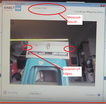
To measure the distance across the tool box, the user needs to collect 2 points as shown in the image.  After the user has taken the 2 points, the result will show up in the top edit box as shown.

Theory of the operation

Threshold
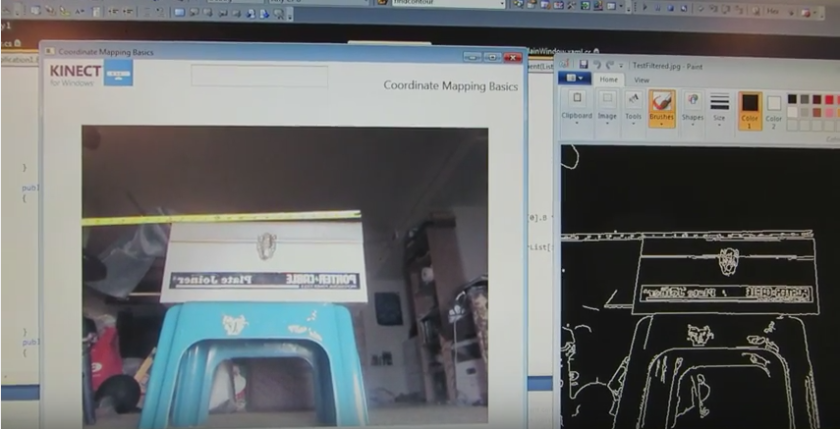
After the Kinect has collected the image, the software uses Canny Edge Detection to generate the edges of the object.  The image on the right is the processed image after the Canny Edge Detector was applied.

Edge Detection

EdgeDetection

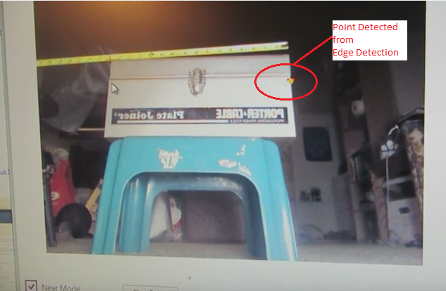
The actual edge detection is done in the black and white image. To get the point on the edge;

  • The user selects a line of pixels perpendicular to the edge know as the Region of Interest.  This process returns an array of pixel intensities.
  • The location of the edge occurs where the pixel intensity has the greatest difference between adjacent pixels.  For example if the array returned { 0, 0, 0, 200, 10, 40 }.  The location of the edge is where the intensity goes from 0 to 200.

C# Code for Calculating Distance

The code works by the user clicking the mouse button in the video window to get a point in the image.  The mouse click returns the depthPoint from the image.  The point is converted to a 3D space by mapping the point to a Skeleton point.  After the user has attained 2 points, the distance between the points is calculated by the SQRT ((P1.x-P2.x)^2+(P1.y-P2.y)^2+(P1.z-P2.z)^2).

The following C# code shows the process of getting a point from the video and converting it to a 3d point.

{

           position = GetEdgePoint(MaskedColor, overlayImage);
            MapColorFrameToDepthFrame(ColorFormat,
DepthFormat,
this.depthPixels,
depthPoints);
            int af = (int)position.X + ((int)position.Y * 640);
            int depth = depthPixels[af].Depth;
DepthImagePoint depthPoint = new DepthImagePoint();
depthPoint.X = (int)depthPoints[af].X;
depthPoint.Y = (int)depthPoints[af].Y;
depthPoint.Depth = (int)depthPoints[af].Depth;
             if (this._PointNumber == 0)
{
_sPoint1 = MapDepthPointToSkeletonPoint(DepthFormat, depthPoint);             }
            if (this._PointNumber == 1)
{
_sPoint2 = MapDepthPointToSkeletonPoint(DepthFormat, depthPoint);
            }
            if (this._PointNumber > 1)
{
                double distance = 0.0;
distance = Math.Pow(_sPoint1.X – _sPoint2.X, 2) +
Math.Pow(_sPoint1.Y – _sPoint2.Y, 2);
Math.Pow(_sPoint1.Z – _sPoint2.Z, 2);
distance = Math.Sqrt(distance)*1000.0/25.4;
txtDistance.Text = distance.ToString();
}


 References

A good reference for the project was “Beginning Kinect Programming with the Microsoft SDK” by Jarret Webb and James Ashley.  The book is well written and has great examples.  Chapter 8 “Beyond the Basics” has a lot of good utilities that were very useful.  One example was converting between Bitmapsource and Bitmaps.

Limitations

The one limitation of the application; the results were not always consistent.  Sometimes the edge detection did not detect the point, so you would need to take the point again. I am not sure if it is because the camera was not calibrated or the Depth and Image buffers were not aligned.

Video

Posted in Computer Vision

OpenCV Augmented Reality Demo

Introduction

You are probably wondering what does Augmented Reality have to due with CNC milling.  Augmented Reality would enhance the usability of the mill by using a camera.  The camera would tell the mill where to move by detecting markers placed on the material to be machined.  I came across a lot articles online about Marker Tracking.  The goal is to have the camera detect the marker and calculate the postion on the material.  Next, the mill would move to the position and start cutting the material.

Open Source Augmented Reality

There are many Augmented Reality libraries out there.  The 3 libraries that I looked at were; ArUco toolkit, ARToolkit, and Glyph.  I was looking for a library that would support 64 bit Windows and was based on OpenCV or Emgu.  I chose the ArUco library for the marker tracking ability.  For more information on the ArUco library refer to the following link;

http://www.uco.es/investiga/grupos/ava/node/26

https://sourceforge.net/projects/aruco/

There is a learning curve with the library, but there are many simple examples to start with.  Calibrating the camera took a little time to get working that was me not the library.

The ARToolkit is a good library to use also.  The ARToolkit also worked with the Unity Game Engine.  The game engine looked like a popular package to use with Augmented Reality.  The next area to look at would be understand how to integrate Unity with the project.

The versions of software I was using;

  • OpenCV Library 3.10
  • ArUco Library 1.3
  • ARToolkit V5.x
  • Visual Studio 2012
  • Windows 7 x64
  • Kinect SDK 1.8

Kinect Camera

The project started out using a Logitech web camera.  Once the software was working the next phase was to use the Kinect camera.  As the project progresses, the Kinect would be used to calculate the position of the marker in 3D space.  The camera is able to measure the distance because it includes a depth buffer along with  an image buffer.  A  plain old web camera only has an image buffer.  With the depth and image buffers aligned in the video, a user can click mouse button in the viďeo window to get the distance reading (Z).  The X and Y position would be derived from the measurement (Not sure about the accuracy of measurements).

Marker Tracking with the Kinect

The video below starts out with the Kinect tracking one marker.  The second half of the video shows the Kinect tracking 24 markers.  Initially the Kinect would only track 6 markers, because the image was reversed horizontally.  This meant that the markers were also reversed.  6 markers were detected, because their orientation was symmetrical horizontally. Once the orientation of the video was corrected, then the Kinect detected the 24 markers.

The application is written in C++.  The application is one of the sample applications provided with the library, but it had to be modified for the Kinect.  Most of the work was getting the library to work with the OpenCV 3.1 and the Kinect SDK 1.8.

Most of the OpenCV applications I came across used a web cam, but not the Kinect.  The code used for collecting images with the Kinect came from a blog by Rozengain “A Creative Technology Company Specialized in 3D”.  The web site is http://www.rozengain.com

The next step is to make a version that works in WPF and C#.