This section is very important for the Detecting/tracking the markers. It also affects the accuracy of the camera orientation. This article assumes you have experience with Visual Studio 2015.
Watch OpenCV Basics on Camera Calibration
This the minimum training needed to calibrate the camera. George Lecakes provides the tutorial. There are 4 parts to calibration.
OpenCV Basics 14 on Camera Calibration Part 1
OpenCV Basics 16 on Camera Calibration Part 2
OpenCV Basics 17 on Camera Calibration Part 3
OpenCV Basics 18 on Camera Calibration Part 4
Create a Detection Board for Calibration.
Select the project to create a pattern used for calibration.
Here are the debug setting in VS2015
Cut and paste the settings into VS2015 and run the program
To calibrate the camera, place the board in the field of view of the camera. Change the orientation of the camera. The youtube video OpenCV Basics 17 on Camera Calibration Part 3 shows how to calibrate the camera. It is not hard.
The purpose of this article is to explain how to update your old CNC machine. Also a another reason for this article is to record what I did so I can reference it later. I guarantee, 6 months from now I won’t remember. This article was written assuming you have some experience with the KFLOP motion controller or any other motion controller. Also, good wiring skills are needed to connect encoder/motor to the motion controller.
About the old machine
The machine was old, but it was in good condition. The table moved as expected. You can turn the lead screws on each axis and move the axis. This task was to make sure that the lead screws were not locked.
DC Servo Motor
This is my 3rd machine that I have worked on. Refurbishing the machine went faster than expected, because most of the parts were still working. The machine used old DC Servo motors with analog tachometers. After all the machine is over 20 years old. What do you expect from an old machine?
Modifying DC Servo Motor and Analog Tachometer
To update the motors, I removed the tachometers and replace them with encoders. It was a very small investment in time and money.
The image below shows the original motor with tachometer.
Motor and Analog Tachometer
Replacing the Tachometer with Encoder.
The image below shows the motor with the encoder. Replacing the tachometers with encoders simplified the motor. I used the AMT102 encoders from CUI, Inc.
Incorporating KFLOP and Snap Amp
I used the Dynomotion KFLOP Motion Controller again for this project. What is different with this new machine from the previous CNC machines? I used the Dynomotion Snap Amp to drive the servo motors instead of the Gecko drives. This turned out to be a good decision;
The minor downside of the Snap Amp; it costs more than the Geckos. The Snap Amp costs $400, but controls 4 axes. If you only need 3 axis, 3 Geckos will cost you $114.95/each for a total for $344.85.
The Snap Amp was easier to wire than the Geckos.
Dynomotion provides all software to tune the PID parameters for the Snap Amp. Tuning the Amplifier was done without any manual adjustments to the hardware. The Gecko drives required manually tuning by adjusting a potentiometer on the drive.
XBox Joystick
We are using the XBox Game Controller to move the machine. It works well for what I want it to do. The good thing about the controller, you can customize the joystick to do more than just move the machine. In this demonstration, functionality was added to the X, Y, B button to zero out the axes.
Just a tip. If you don’t want to spend a lot of money on XBox Joystick, you can buy one at Goodwill for $6 or $7. I bought my second joystick there. It works as good as the newer one.
Getting the Motion Control System to work
This took me about a few hours to get the first motor to move because I was a little sloppy with the wiring. Make sure your wiring is good especially between the encoders and the KFLOP. Bad wiring will cause the machine to move unexpectedly. After working on the machine, I am a firm believer in using the e-Stop. If you machine goes out of control; just hit the e-stop. Whatever you do, take your time with the wiring and invest in good crimping tools
Also, It took me a while to figure how to write the C program to move the stage.
This code will allow you move the motors from the KMotion Step Response dialog. I would test each axis.
How to Create the C Program for the KFLOP and Snap Amp.
Creating the C program to control the SnapAmp was a little tricky. I am assuming your machine has 3 axis. Basically, I converted InitKStep3Axis.c program to control the Snap Amp.
Here are the steps.
Copy InitKStep3Axis.c in C:\KMotion433\C Programs\KStep to C:\KMotion433\C Programs\SnapAmp.
Once you have the program you can start tuning the servos. Dynomotion provides all of the software to tune the system. Of course you need to wire the encoders to the KFLOP.
Before you apply power to the motors, run the KMotion.exe and hit the “Axis” menu. This page displays the status of the each axis via encoders. When you turn the motors manually, you will see the counts change for each axis.
Next wire the power up to the motors and the Snap Amp.
Here are the steps.
Turn on the Power. Run Kmotion.exe.
Open, Compile and Run the initSnapAmp3Axis.c.
3. Open the Config Dialog.
4. Open the Step Response Dialog.
5. On the Step Response Dialog under the “servo” box.
Hit the “disable” button to disable the servo amp.
Hit the “Zero” button.
Hit the “Enable” button to re-enable the servo amp.
6. To Tune hit the Step button. You should see the output as shown above.
7. Change the P, D, I values in the order specified until you get the output as shown below
8. Repeat the steps for the other axes. For more information refer to the KFLOP manual.
To get the most benefit from this blog you should have some background in the following areas; Computer Vision applications with OpenCV and marker tracking, C#/C++ programming.
Introduction
In this article I will demonstrate how to develop an Augmented Reality (AR) application to move your CNC machine. I call application the AR Joystick. The AR Joystick interfaces with a camera and displays the video. It operates by searching for markers on the machine. When it detects the markers, the app draws a green box around markers and draws the lines for the X and Y Axis. If the box is not drawn the marker is not detected. The markers determine where the machine can move.
The initial idea came from the book “Arduino Computer Vision Programming”, Chapter 9 “Building a Click-To-Go Robot”, by Ozen Ozkaya. The chapter explains how to write an video application that moves a robot from a video window using the mouse.
About this blog subject
This blog could easily generate at least 10 additional blogs. I will make a series for the additional blogs and make this blog an overview, but I will spend more time talking about the software. Otherwise the blog will be too long for anyone to read.
The Setup for the AR Joystick
Here are the parts used.
PC running Windows 10 x64
OpenCV 3.2.0 – Aruco (Augmented Reality Library from the University of Cordoba)
Visual Studio 2015 Community Edition
An old CNC machine.
Dynomotion KFLOP motion controller.
Dynomotion Snap Amp DC Servo drive.
Logitech WebCam
2 Laser Markers from Harbor Freight
XBox Joystick.
3 AMT102 encoders.
Power supply 24 VDC.
Refurbishing an old CNC machine
This is my 3rd machine that I have worked on. Refurbishing the machine went faster than expected, because most of the parts were still working. Only the DC Servo motors were outdated, they were using analog tachometers. The tachometers were replaced with Encoders from CUI, Inc.
I used the Dynomotion KFLOP Motion Controller again for this project. What is different with this new machine between the previous CNC machine? I used the Dynomotion Snap Amp to drive the servo motors instead of the Gecko drives. The Snap Amp was easier to use.
Writing the software for the AR Joystick
The AR joystick uses 2 programs; CNC Machine Client, and CNC Video Server program. The client is written in C#. The server is written in C++. The server program tracks the markers to set up the origin, X and Y axes, and tells the client where to move.
CNC Machine Client program with the Xbox Game Controller.
The CNC Machine client software uses the Xbox Game Controller to move the machine.
The client moves the machine and displays the XYZ location. When the client is connected to server, the server tells it where to move. When it is not connected to the server, Xbox joystick controls the client. To connect the client to the server. Hit the “Connect Pipe” button.
This is what the client looks like.
CNC Machine client
The CNC Video Server Program.
This is where the fun begins. This is where we apply Augmented Reality and Robot Computer Vision to the project.
The “CNC Video Server” shows 2 images of the same scene. The image on the right is the perspective view. The image on the left is the 2D view. The server acquires the video as shown on the right and transforms the image into 2D using the warpPerspective OpenCv command.
The image on the left is where the user controls the machine movements. All the user has to do is click the mouse in the video and the machine moves!!
CNC Video Server
Augmented Reality ARUCO markers to move the machine
The main purpose of the server is to track 4 ARUCO Markers to set up a machine coordinate system based on their orientation. Each marker has a specific purpose;
Marker 1 is the origin.
Marker 3 specifies the X-axis.
Marker 2 specifies the Y-axis.
Marker 4 is optional.
The green lines in the video are the X and Y axis. The red lines you see are projected from the laser markers mounted to the machine. These markers show the actual machine position in the live video.
Video Server 3D Perspective View
Video Server 2D View
The server aligns the perspective image into a 2D image. The distance between the markers is known to the server. It defines the scaling, pixels/mms, for each axis.
When the user clicks the mouse in the 2D window, the server detects the pixel XY location and converts XY pixels into inches. Next the program sends XY values to the CNC Client. When the client receives the XY values, it will move the machine in the specified XY coordinates.
Applying a perspective Transform and warping the Live Video.
The OpenCV Server displays 2 images of the same scene. One window shows the perspective view the other shows a 2D view. Here is the OpenCV snippet that transforms the video.
The vector pts_corners are the 4 center points of the AR markers in the perspective view. The term “vector” refers to the C++ Standard Template Library data structure.
The vector pts_dst are the 4 center points of the AR markers but in the 2D view. Both of these vectors are used to find the Homography matrix. This matrix is used to map the 3D image onto a 2D image.
Mat h = findHomography(pts_corners, pts_dst);
warpPerspective(imageCopy, im_out, h, imageCopy.size());
imshow(“XYView”, im_out);
Handling Mouse Events in OpenCV
The OpenCV code snippet for handling mouse events is implemented by using a callback. A callback is a pointer to a function. When the user clicks the mouse in the 2D window, the server generates an event to the callback function to process. The callback function returns the location of the mouse. The code is very common on other blogs and articles. The code will look like the following snippet.
setMouseCallback(“XYView”, CallBackFunc, &stagePt);
The callback function will look something like
void CallBackFunc(int event, int x, int y, int flags, void* ptr)
{
if (event == EVENT_LBUTTONDOWN)
{
// Do something
}
}
Details that I am leaving out for Now
I am leaving out a lot of details. The details will be covered in the next blogs if someone want more information. Otherwise the blog would be too long.
How to Use the Omron EE-SX671 Limit Switches (Part 2)
This article explains how to use these switches.
Creating ARUCO Markers for the Coordinate System (Part 3)
You will need to create the 3 or 4 markers for coordinate system. For more information refer to OpenCV Basics 21-Aruco Marker Tracking on youtube.
Camera Calibration (Part 4)
Calibration is very important for software. Without calibration the machine movements would not be as accurate. For more information refer to OpenCV Basics 14-Camera Calibration on youtube.
Updating an Old CNC Machine: Servo Tuning for KFLOP and Snap Amp (Part 5)
If anyone is interested in a blog about this subject let me know.
Video camera Controller
The camera is simple Logitech 1080p webcam. It costs about $70. To write software to control camera refer to the OpenCV Basics 12- Webcam & Video Capture on youtube.
Using Pipes to communicate between the programs.
The named pipes were used for the Client and Server to talk to each other.
Limitations:
I need to emphasize; THE SOFTWARE IS NOT PRODUCTION CODE. I would not put the code in mission critical applications. The software is only a prototype and was only written to prove a simple concept. Also accuracy of the stage movements is not great.
Credits
AMT102 Encoders from CUI Inc.
George Lecakes – OpenCV Tutorial on YouTube. I highly recommend these videos. There are 21 videos each one is about 10 to 15 minutes long.
OpenCV Basics 01- Getting setup in Visual Studio 2015 for Windows Desktop.
OpenCV Basics 11- Building OpenCV Contribute to CMAKE.
OpenCV Basics 12- Webcam & Video Capture.
OpenCV Basics 14-Camera Calibration Part 1, Part 2, Part 3, Part 4
The purpose of this blog is to demonstrate how to measure distance with the Kinect. The project uses Emgu (Computer Vision Library). Emgu is the C# version of OpenCV (Open Computer Vision). The following software example was taken from the Kinect SDK 1.8 Coordinate Mapping sample. The sample was modified to measure distance using the Depth Buffer.
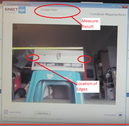
How to take the Measurement
To measure the distance across the tool box, the user needs to collect 2 points as shown in the image. After the user has taken the 2 points, the result will show up in the top edit box as shown.
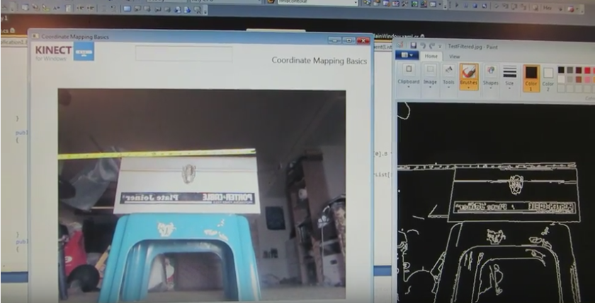
Theory of the operation
After the Kinect has collected the image, the software uses Canny Edge Detection to generate the edges of the object. The image on the right is the processed image after the Canny Edge Detector was applied.
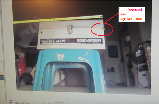
Edge Detection
The actual edge detection is done in the black and white image. To get the point on the edge;
The user selects a line of pixels perpendicular to the edge know as the Region of Interest. This process returns an array of pixel intensities.
The location of the edge occurs where the pixel intensity has the greatest difference between adjacent pixels. For example if the array returned { 0, 0, 0, 200, 10, 40 }. The location of the edge is where the intensity goes from 0 to 200.
C# Code for Calculating Distance
The code works by the user clicking the mouse button in the video window to get a point in the image. The mouse click returns the depthPoint from the image. The point is converted to a 3D space by mapping the point to a Skeleton point. After the user has attained 2 points, the distance between the points is calculated by the SQRT ((P1.x-P2.x)^2+(P1.y-P2.y)^2+(P1.z-P2.z)^2).
The following C# code shows the process of getting a point from the video and converting it to a 3d point.
{
position = GetEdgePoint(MaskedColor, overlayImage);
A good reference for the project was “Beginning Kinect Programming with the Microsoft SDK” by Jarret Webb and James Ashley. The book is well written and has great examples. Chapter 8 “Beyond the Basics” has a lot of good utilities that were very useful. One example was converting between Bitmapsource and Bitmaps.
Limitations
The one limitation of the application; the results were not always consistent. Sometimes the edge detection did not detect the point, so you would need to take the point again. I am not sure if it is because the camera was not calibrated or the Depth and Image buffers were not aligned.
You are probably wondering what does Augmented Reality have to due with CNC milling. Augmented Reality would enhance the usability of the mill by using a camera. The camera would tell the mill where to move by detecting markers placed on the material to be machined. I came across a lot articles online about Marker Tracking. The goal is to have the camera detect the marker and calculate the postion on the material. Next, the mill would move to the position and start cutting the material.
Open Source Augmented Reality
There are many Augmented Reality libraries out there. The 3 libraries that I looked at were; ArUco toolkit, ARToolkit, and Glyph. I was looking for a library that would support 64 bit Windows and was based on OpenCV or Emgu. I chose the ArUco library for the marker tracking ability. For more information on the ArUco library refer to the following link;
http://www.uco.es/investiga/grupos/ava/node/26
https://sourceforge.net/projects/aruco/
There is a learning curve with the library, but there are many simple examples to start with. Calibrating the camera took a little time to get working that was me not the library.
The ARToolkit is a good library to use also. The ARToolkit also worked with the Unity Game Engine. The game engine looked like a popular package to use with Augmented Reality. The next area to look at would be understand how to integrate Unity with the project.
The versions of software I was using;
OpenCV Library 3.10
ArUco Library 1.3
ARToolkit V5.x
Visual Studio 2012
Windows 7 x64
Kinect SDK 1.8
Kinect Camera
The project started out using a Logitech web camera. Once the software was working the next phase was to use the Kinect camera. As the project progresses, the Kinect would be used to calculate the position of the marker in 3D space. The camera is able to measure the distance because it includes a depth buffer along with an image buffer. A plain old web camera only has an image buffer. With the depth and image buffers aligned in the video, a user can click mouse button in the viďeo window to get the distance reading (Z). The X and Y position would be derived from the measurement (Not sure about the accuracy of measurements).
Marker Tracking with the Kinect
The video below starts out with the Kinect tracking one marker. The second half of the video shows the Kinect tracking 24 markers. Initially the Kinect would only track 6 markers, because the image was reversed horizontally. This meant that the markers were also reversed. 6 markers were detected, because their orientation was symmetrical horizontally. Once the orientation of the video was corrected, then the Kinect detected the 24 markers.
The application is written in C++. The application is one of the sample applications provided with the library, but it had to be modified for the Kinect. Most of the work was getting the library to work with the OpenCV 3.1 and the Kinect SDK 1.8.
Most of the OpenCV applications I came across used a web cam, but not the Kinect. The code used for collecting images with the Kinect came from a blog by Rozengain “A Creative Technology Company Specialized in 3D”. The web site is http://www.rozengain.com
The next step is to make a version that works in WPF and C#.


 After the Kinect has collected the image, the software uses Canny Edge Detection to generate the edges of the object. The image on the right is the processed image after the Canny Edge Detector was applied.